Odd jobs
If it didn't fit in anywhere in any previous blog entry, I actually bothered my ass to do it and it was done during the months before the 2018 season: it is here.

I have many plans for the VFR but many will have to wait for later in the season as funds trickle in.
In the mean time, everything that was deemed necessary, or the parts came up cheap, got done.
Going keyless
Keys are a pain as you can leave them in the bar or they can fall out of the bike on track which sucks, even if the stories that come out of such things are rather funny.
This will require an ignition switch mod and fuel tank cap swap.
Fuel Cap
First to get the chop was the fuel cap.
The stock fuel cap it retained by a triangle of three bolts that are accompanied by four more decorative bolts. These have the outward look of M6 allen bolts but in reality are stepped down to M4 thread. This is just a stupid annoyance but when you go and loose these tapered bolts and try and refit the cap what do you do? Well you use off the shelf M4 bolts which are far too small and just look daft. Now make the cap look thirty years old, sticky to use and you are left with the grot that was fitted to my bike.
 If you look for fuel caps for the RC24; you wont find a great deal other than a pattern stock cap.
Now I have owned enough Hondas to know that this design of fuel cap is fitted to next to every bike I have owned so I thought I would just look for something designed for a Honda.
This brought up a race cap for a CBR600RR sat at £20 on good old Ebizzle. Nobody else fancied it and I won it for peanuts.
The number of fasteners was the same but the bolt pattern was fractionally different. I used a drill and carefully repainted the inside to shift the holes along a bit, you can hardly tell.
Ignition
Removing the key from the ignition is easy but taking the lock with it takes a touch more planning.
I first thought of keeping it simple and just getting a multiple point switch to replace the ignition barrel.
Not liking to keep things simple I instead decided to pair down the whole wiring loom to just the essential systems I needed and switching just the power.
With the wiring loom removed and the aid of a haynes manual; I picked off side lights, the fan, side stand switch and indicators to list a few. It was pretty straight forward in actual fact with the only complication being that the fuel pump cut off needed a bridge to allow for the removed side stand switch.
As for the ignition itself; it was down to two wires which I used a 2>2 toggle switch for only because I had initially intended to include the radiator fan initially.
Thanks to all of my wiring removal; I only had one fuse left in the fuse box so that too was removed in favour of a simple tube type fuse holder. I hoped to later swap this for a tidier looking contact breaker.
HT leads
The insulation was split on one of the HT leads so I decided to change them all.
I ordered a roll of HT lead in red (because it looked cool on the CBR600 F3 I had recently broken) and eventually the day came when I was bored enough to go at this job.
The cap on the coil pack unscrews allowing the HT lead to be pulled out of the socket. Next I unscrewed the HT lead from the cap. This proved to be an error as the lead is actually soldered to a small washer in the cap but it worked and as I am used to NGK caps wasn't stupid to do (right?).

 I had intended to reuse the caps as they looked pretty new but whilst giving this first one a look over I spotted it was disassembleable so I went ahead and monopolised on this.
By jamming a flat blade screwdriver in the plug end of the cap and giving it a few turns; the brass plug holder came out with its spring attached. This was followed by a resistor in a rubber sleeve and in my case a washer covered in solder and wire strands.
I cut a length of HT lead, stripped down one end and fed it into the HT cap.
The washer was then placed in a vice width ways and a powerful soldering station was used to melt the solder allowing me to poke out the wire strands and old solder.
The wire from the new HT lead was then fed in and its strands splayed.
Again, I used a high heat setting, and heated the wire/ washer combo before feeding in a generous amount of solder till it formed a dome.
 Excess strands were then cut away and the lead was then pulled back into the cap till the washer seated. This was followed by a freshly cleaned resistor (the bottoms of all the resistors were nearly all coated in rust) and then the plug holder was screwed in to secure the lot.
The other end of the HT lead was then 'pricked' with a scribe so it would impale on the spike in the coil pack. The coil pack cap was threaded onto the lead then the coil pack was offered up and the cap was screwed on.
Some pre-printed dyno tape was applied to each lead with corresponding numbers for its cylinder to, hopefully, stop me screwing up which cap goes where.
This process was repeated no less than three more times (only I didn't try unscrewing the HT lead from the cap) giving me 4 fresh HT leads ready to help the plugs zap some fuel.
Some NGK iridium spark plugs would soon follow to ensure the most bang for my buck, almost literally.
Mind the gap
 Judging by the plentiful coating of fur on this machine, the valve gaps hadn't been done in a while, if ever.
To gain access for this job it helps to remove the tank, airbox, rear subframe, radiator, fan shield and probably a whole bunch of other stuff that I had off anyway. Suffice to say it is a lot!
With access made, the two rocker covers come off with 8 bolts and a little nudge with a hammer to break years of being stuck together.

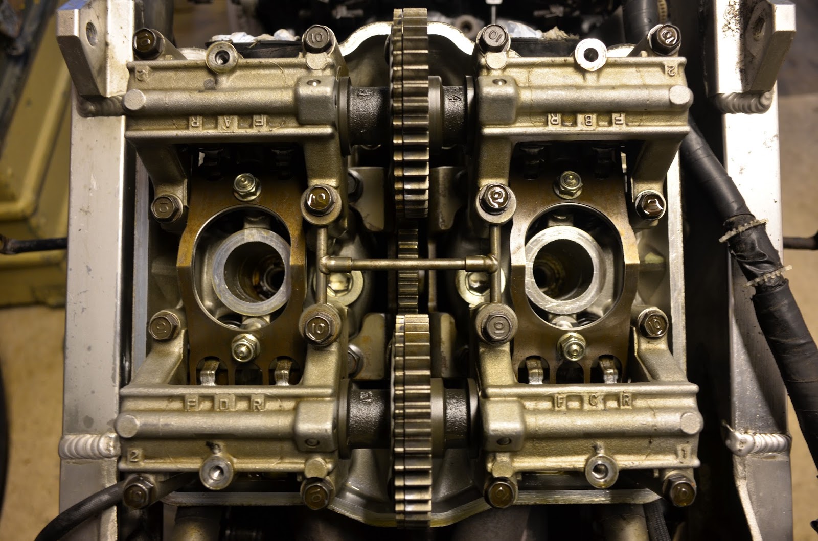
Underneath I found a clean and mechanically pretty sound looking pair cylinder heads.
Being an earlier bike; I had the joys of tappets. I like these things as they are easy to work on, sod service intervals and noise if it is easier to do!
The only other thing that needed removing was the generator cover to allow be to turn the engine over.To check the valve gaps I used a set of long feeler gauges and turned the engine using the flywheel nut.
As it turned out; the gaps were pretty close to perfect, if slightly on the closed side so failing safe. I like that and so do the pistons.


On the left is the inlet and right is exhaust incase you wanted to know what they looked like.
Adjusting is a simple case or loosening the lock nut and turning the screw to the desired clearance.


Comments
Post a Comment